
What is this about?
The ASUS S200E is a natty semi-ultrabook (if Microsoft will forgive this description) with touch screen and Windows 8. Pity it does not have Linux instead but W8 is at least usable with a modest size of touch screen. The keyboard of the laptop illustrated here had been doused with a sugary drink some three months earlier and a bunch of keys were reluctant to come up after pressing. Access for cleaning required substantial "demolition".
This model has tightly packed components and a thin hard drive to enable the pleasing slim line effect. Memory is soldered but the drive can be replaced fairly easily. So can the battery module which has an unusual connector and numerous screws.
The keyboard itself is sandwiched between two aluminium plates, the top one glued to a plastic moulding and the bottom one secured firmly to this moulding by plastic "rivets" (heat sealed).
Cleaning
The keyboard composite component was not taken apart but it was possible after the main disassembly to suspend the keyboard portion in water without inundating other electronics. It was lowered gently into a weak washing up liquid solution first, this being replaced after 12 hours with plain water and left for another 12 hours. During both "soakings" the keys were gently operated from time to time to eject trapped air and stir the water locally. After drying (vertically still) for a couple of days on a warm radiator the keyboard operated perfectly.
Tear down
The description here is in "tear down" order though the pictures were taken during reassembly. Be aware that various different sizes of screw are used, even in the same apparent group, so separate them carefully and note which come from where. You could put them in tubs labelled "A", "B" etc. and mark the positions on printed copies of the pictures below.
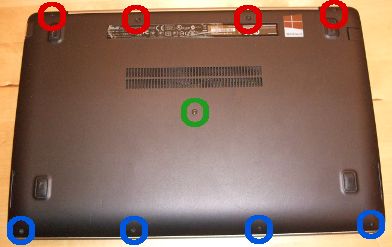
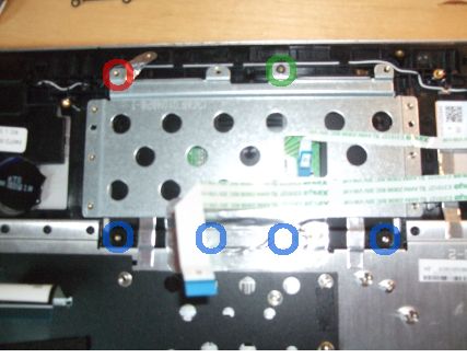
The three different colour circles indicate the different screw lengths used to hold the back cover. The centre one (green circle) is only slightly longer that the "reds", so take care. The blues are short and slightly angled.
Remove screws and carefully prise off the base with a thin blade. Probably best to start at a hinge. Once opening starts use of lolly-pop (popsickle?) sticks to hold parts open and lever more open is suggested, but the clips are easier to get open than some.
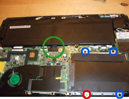
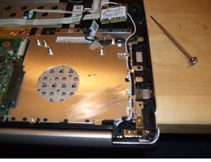
Removing the battery and hard drive are fairly easy. Note that the hard drive cover has just three screws (blue circles). The red circle position is for one of the cover screws you have already removed. Be careful with the battery connection (green circle). The "plug" lifts vertically from the motherboard.
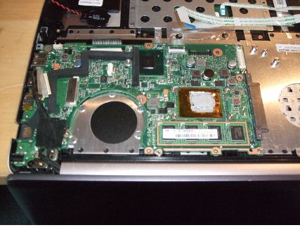
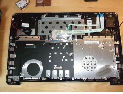
Look, no battery! The circled hole is where the centre back cover screw goes, so don't insert a screw here when reassembling. Disconnect the various cables to the two motherboard sections (some "flip up" clips, possibly some "slide out" clips and some (non-ribbon cable) "yank out carefully" ones. Also take out the wireless module (top right here - one screw) but you can leave the antenna cables plugged to it.
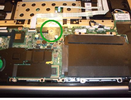
Now note the positions and sizes of the screws for the small (L shaped) motherboard section and remove it. Note that it has a socket on the left connecting it to the main board. Detach it by lifting vertically.
Note how the antenna and near by cables to the same hinge run and lift them out, leaving the wireless module attached to them.
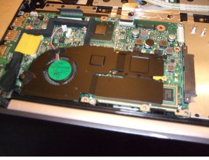
The heat sink and fan module is fixed by five screws, four identical (through the springy "arms") and one different. Detach the fan power cable (if not done already). Gently lift the unit out.
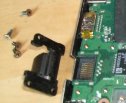
The sprung cover over the ethernet connection must be removed.
The yellow tape here replaces the original clear tape which secured and insulated the video connection. In fact only the right hand side of the clear tape was cut off as the left edge was secured. The video plug slides out to the left (somewhat obstructed by the foam padding strip).
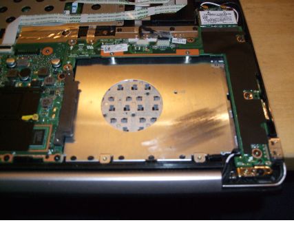
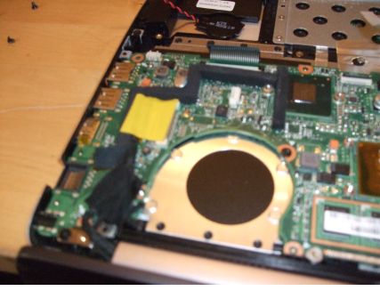
It is now time to unscrew (noting screw positions and lengths) the main motherboad. Remove it. When reassembling the screen modlue must be attached first (by the one screw shown).
Before reassembly the old heat conducting paste should preferably be carefully removed and new applied.
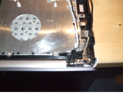
Detach the hinges (one screw each) and remove the screen.
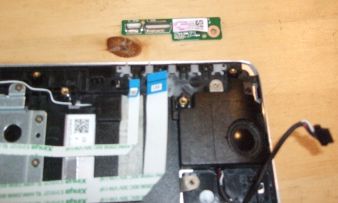
The LED circuit board may be disconnected (lift up catches) and removed. One screw.
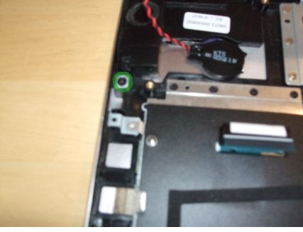
The Kensington Lock point may be partially dismantalled - one screw shewn by green circle. Probably not necessary.
The plate under the touch pad may be removed for access to the touch pad itself, though stuck on earth strapping may be a problem. The plate has 10 screws (e.g. at red and green circle positions). A further 4 identical screws (blue circles) through the plastic near by may secure the pad itself. The red circle position has a an earth strap stuck on top which must be pealed back and later re-positioned.
The keyboard and touch pad now remain as an item. It is the side towards us which was soaked, keeping the touch pad and adjacent speakers clear of the water.
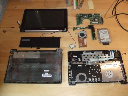
The components spread out.
Reassemble
With care, not too difficult, though on the first attempt the video connection plug and the small USB module cable end were both not fully inserted. Fortunately both are fairly easily accessed.
Use of this material

The above was researched and written by Richard J Bowers (richard at nomaz dot co dot uk) and is made available for free use under a Creative Commons Attribution-ShareAlike 3.0 Unported License. It is provided in the hope that it will be useful, but no liability can be accepted so use at your own risk - or else ignore this material entirely.